Igniter Tester Component Description
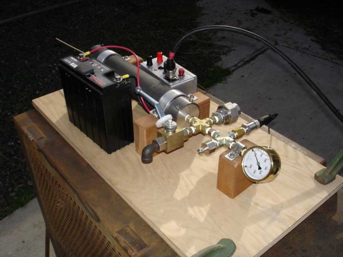
At the 12 o'clock position is the relay box, with continuity test button and buzzer, and cable to remote control switches.
Traveling clockwise:
- The first cross T has a brass shim stock burst diaphragm inside the stainless steel coupling proofed by experiment to burst at 1600psi.
- The next cross T has a 7 micron snubber/filter and the 100 bar (1500psi) Parker pressure transducer (0 to 5v output).
- Next is the 3000 psi oil filled Bourdon tube pressure gauge also connected via a 7 micron snubber/filter used to calibrate the burst diaphragm and to set the initial CO2 pressure for burn rate testing.
- A high pressure disconnect is next to connect to a CO2 tank (max about 650psi) or Argon/CO2 tank (max about 2500psi).
- The high pressure valve is next and used to release pressure after a test.
- Next is the 12volt battery and then the pressure chamber.
The chamber is 4130 alloy steel seamless DOM tubing and has a calculated burst pressure in excess of 3000psi. The end plugs are 6160 T651 aluminum each fastened with 6 10-32 SS SHMS. Double silicone O-rings provide the gas seal each end to a 2000psi design point. All fittings are rated 3000psi.